

Choosing the right Foot Pedal Valve begins with understanding the machine, not the catalog page. A workshop press, pneumatic clamp, and packaging line may all need different control behavior. Consider the operating pressure, port size, flow demand, installation space, and required pedal action. A valve that feels comfortable on a clean test bench may become awkward beside oil, dust, or a guarded machine.
Pneumatic controls specialist Peter Nachtwey once noted, “Good control starts with understanding the complete system, not one component.” His observation applies directly to Foot Pedal Valve selection. Check whether the valve should be normally closed, normally open, or momentary. Confirm the actuator’s response time and the operator’s working position. A broad metal pedal may suit repeated use, while a compact polymer pedal may fit a restricted enclosure. Small details matter.
Safety deserves equal attention. Look for stable mounting holes, clear labeling, suitable materials, and compatibility with the working environment. Do not judge quality by price alone. A cheaper valve can create higher maintenance costs when seals wear quickly or connections leak. This guide cannot predict every site condition. That is a limitation worth admitting. Real machines behave differently.
Before ordering, compare the technical datasheet with the actual installation. Test the pedal under realistic pressure and load. Listen for leaks. Feel for delayed return. Then ask whether operators can use it without stretching, twisting, or removing their attention from the work area. The best Foot Pedal Valve is not merely functional. It is dependable, understandable, and suited to everyday operation.
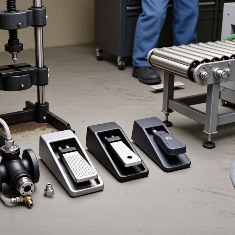
Choosing a foot pedal valve starts with its operating principle, not its appearance. A 3/2 valve controls one single-acting actuator, using supply, output, and exhaust ports. A 4/3 valve manages a double-acting actuator through two working ports. Its center position may block, exhaust, or connect the air paths. That choice affects motion, safety, and cycle control.
Pneumatic foot valves usually use spool or poppet mechanisms. A spool shifts sideways when the pedal moves, directing compressed air through internal passages. A poppet lifts from its seat and can provide quick switching with compact construction.
Momentary models return when the operator releases the pedal. Maintained models stay in position until pressed again. Guarded pedals reduce accidental activation, especially near busy workstations. They are not interchangeable.
Look at pressure, flow, port size, and return force together. A valve rated for 1,000 cycles per hour may fail early if contamination enters the air line. The U.S. Department of Energy’s Improving Compressed Air System Performance report notes that compressed air can represent 10% or more of industrial electricity use, so leakage and unnecessary exhaust deserve attention. MarketsandMarkets reports continued growth in the industrial valves market, driven partly by automation and process control. The number is useful, but it does not select your valve. Measure the cylinder’s required flow and response time. Then check ISO 5599-1 compatibility, pedal ergonomics, and exhaust noise. I still verify real cycle behavior after installation; catalog pressure ratings can hide awkward operator feedback.

Choosing the right foot pedal valve begins with the operator, not the catalog. Observe the real workstation first. Is the operator seated, standing, or moving between stations? A seated operator may need a low-force pedal, while a standing operator needs a stable, slip-resistant platform. Check the required pneumatic pressure, flow rate, cycle frequency, and response time. Dust, oil, water, and metal chips also affect housing, sealing, and tread design.
Control conditions deserve equal attention. A guarded pedal can reduce unintended activation, especially where hands remain near tools or workpieces. The U.S. Bureau of Labor Statistics reported 2.6 million nonfatal workplace injuries and illnesses in private industry during 2023. This figure does not isolate foot controls, but it reinforces the need for task-specific risk assessment. OSHA machine-guarding guidance and ISO 12100 both support evaluating hazards during normal operation, cleaning, adjustment, and foreseeable misuse.
Test it under real conditions. Measure pedal force with a simple gauge, then repeat the test after several hours of operation. Watch for fatigue, accidental contact, delayed valve return, and awkward ankle angles. A return spring that feels acceptable on a workbench may feel harsh after 500 cycles. That is easy to miss. Select the valve only after checking the full circuit, including exhaust behavior and emergency isolation. My practical concern is often overlooked: operators adapt quickly, sometimes defeating a guard because it slows production. That human response must influence the final control design.
Material choice affects service life, feel, and maintenance. Brass suits clean, moderate-duty pneumatic systems and offers reliable machinability. Stainless steel handles moisture, washdown, and corrosive surroundings more confidently. Aluminum keeps the assembly light, but it may not tolerate repeated impact or harsh chemicals. Check the body, pedal, springs, and seals separately. They may use different materials. Seal compatibility with oil, water, and temperature is easy to overlook.
Port size should match the required airflow, not simply the existing tube diameter. A small port can restrict cylinder speed and create pressure loss. An oversized valve may add cost without improving performance. Compare the valve’s flow rating with the actuator’s demand and the length of connected tubing.
Pressure ratings need equal attention. Select a working pressure above the system’s maximum, including temporary surges. Never rely only on the normal gauge reading. I once focused too heavily on pressure and underestimated exhaust flow. That choice worked poorly during rapid cycling.
Tips: Verify thread standards, mounting space, and pedal travel before ordering. Test the valve with the actual seal material and operating fluid when possible. Leave a safety margin for pressure and temperature. Short checks prevent long repairs. Also, inspect the pedal’s return action. A stiff or slow return can affect control, even when the valve body remains within specification. Perfect selection is uncommon; careful verification is better.
Choosing a foot pedal valve begins with compatibility, not appearance. Match the valve to the working medium, pressure range, port size, and operating temperature. Air, water, and hydraulic fluids require different seals and body materials. Check whether the pedal controls one position, two positions, or a momentary return function. A small mismatch can cause slow response, leakage, or unexpected movement.
Safety features deserve close inspection. A guarded pedal can reduce accidental activation near crowded workstations. A spring-return design may stop flow when the operator removes pressure, but it is not automatically fail-safe. Apply the risk-assessment principles in ISO 12100 and review control reliability under ISO 13849-1. The U.S. Bureau of Labor Statistics recorded about 2.6 million nonfatal workplace injuries in private industry during 2023. That figure supports careful control selection, even though a pedal valve is only one part of machine safety.
Installation needs are easy to underestimate. Confirm the mounting surface, pedal clearance, tubing route, and access for cleaning. Keep hoses away from sharp edges and walking paths. Test connections at low pressure before normal operation, then check for leaks and unintended cycling. Lockout procedures still matter during adjustment. I have seen installations fail because the pedal sat too close to a chair base. That detail seems minor, but it changes how people use the control. Recheck the layout after a trial shift.
Compare common pneumatic foot pedal valve configurations by circuit function and port count. Always verify working pressure, thread standard, media compatibility, guarding, return action, and mounting space before installation.
A 3/2 valve is typically used for a single-acting actuator or spring-return circuit, while a 5/2 valve is commonly used for a double-acting actuator. A 4/3 valve provides three spool positions for more flexible directional control. The correct choice depends on the circuit diagram, pressure rating, connection type, safety requirements, and available installation space.
How to Choose the Right Foot Pedal Valve?
A foot pedal valve should be judged by service conditions, not purchase price. In maintenance inspections, dust often collects around the pedal hinge and exhaust port. That debris can increase operating force and delay valve return. Choose a design with protected moving parts, replaceable seals, and easy access for cleaning. The U.S. Department of Energy reports that compressed-air leaks can waste 20–30% of compressor output in poorly maintained systems. A leaking valve can quietly add to that loss.
Reliability also depends on duty cycle. Record daily actuations, air pressure, moisture exposure, and operator handling before selecting a valve. A metal body may tolerate impacts better, while polymer components can reduce weight and corrosion risk. Neither option is automatically superior. The wrong assumption becomes expensive.
Total cost includes labor, downtime, spare parts, and air consumption. The DOE Operations and Maintenance Best Practices Guide links preventive maintenance with measurable reductions in operating costs and equipment failures. Use that principle in the purchasing review. Compare seal replacement time, inspection intervals, and the cost of an unexpected stoppage. A simple valve may appear cheaper, yet a difficult repair can erase the saving within months. Keep a small maintenance log. It may reveal that the selected model works well, but only under cleaner conditions than expected.
Comparison of common foot-operated valve configurations for industrial pneumatic applications. Actual service life and cost depend on duty cycle, air quality, installation, and operating environment.
| Valve Configuration | Typical Operating Function | Recommended Air Quality | Routine Maintenance | Reliability in Frequent-Cycle Use | Typical Service-Life Range | Indicative Purchase Cost | Estimated 5-Year Total Cost | Best Selection Scenario |
|---|---|---|---|---|---|---|---|---|
| 3/2-Way, Spring-Return Foot Valve | Controls a single-acting actuator or provides a simple on/off pneumatic signal. | Filtered air, typically 5–40 μm filtration; dry, clean air is preferred. | Inspect the pedal, spring, seals, and fittings every 6–12 months; replace worn seals as needed. | High | 5–10 years in moderate industrial service | US$35–100 | US$70–220 | Simple machines where the pedal must return automatically when released. |
| 3/2-Way, Detented Foot Valve | Maintains the selected pneumatic state until the pedal is pressed again. | Clean, filtered air; lubrication should follow the valve manufacturer's instructions. | Check the locking mechanism, pedal alignment, seals, and mounting hardware every 6–12 months. | Medium–High | 4–8 years in moderate to high cycle service | US$45–120 | US$95–260 | Applications requiring hands-free state retention without continuous foot pressure. |
| 5/2-Way, Spring-Return Foot Valve | Directs air to either side of a double-acting cylinder and returns to its default position when released. | Filtered and regulated air; moisture control is important for reliable spool movement. | Inspect the spool action, pedal return spring, exhaust ports, and tubing every 6–12 months. | High | 5–10 years in properly maintained systems | US$50–140 | US$100–300 | Double-acting actuators that require a predictable fail-to-default action. |
| 5/2-Way, Detented Foot Valve | Alternates a double-acting actuator between two positions and holds the selected state. | Clean, dry, filtered air with stable operating pressure. | Inspect detent wear, spool movement, pedal hardware, seals, and exhaust silencers every 3–6 months. | Medium–High | 4–8 years, depending on cycle frequency and contamination | US$65–170 | US$130–370 | Repeated forward/reverse operation where maintaining the last command is useful. |
| Guarded Safety Foot Valve | Provides guarded foot control and may require deliberate release or reset actions to reduce accidental operation. | Clean, dry, filtered air; contamination can affect safety-related movement. | Test the guard, reset function, return mechanism, mounting, and valve response at least every 3 months. | High | 5–10 years with documented inspection and timely replacement of wear parts | US$90–250 | US$180–520 | Presses, fixtures, and machinery where accidental pedal activation is a significant risk. |
| Pilot-Operated Foot Valve | Uses a low-force pedal signal to control a higher-flow pneumatic circuit or remote valve. | Very clean, dry, filtered air; pilot passages are sensitive to oil, water, and particles. | Check pilot response, signal tubing, seals, and exhaust restrictions every 3–6 months. | Medium | 3–7 years when air preparation is well controlled | US$80–220 | US$180–480 | High-flow circuits or installations where reduced pedal force is important. |
| Heavy-Duty Metal Foot Valve | Provides manual pneumatic control in demanding environments with frequent operator use. | Filtered air; corrosion protection and drainage are important in wet or dirty areas. | Clean the pedal and housing, inspect corrosion and seals, and check fasteners every 3–6 months. | High | 7–12 years in suitable industrial conditions | US$100–300 | US$190–560 | High-cycle production areas, abrasive environments, or applications needing a robust enclosure. |
| Compact Polymer Foot Valve | Offers basic directional control where low weight, compact size, and lower initial cost are priorities. | Filtered air; avoid temperatures, chemicals, and impact loads outside the housing specification. | Inspect the housing, pedal hinge, seals, and mounting points every 6–12 months. | Medium | 3–7 years in light to moderate service | US$25–80 | US$60–190 | Light-duty equipment, clean work areas, and cost-sensitive installations. |
Selection rule: Choose the valve configuration first according to actuator function and required safety behavior. Then verify port size, operating pressure, flow capacity, temperature range, pedal ergonomics, environmental protection, replacement-part availability, and the cost of planned inspections and downtime.

We have over 30 years of experience in designing complete hydraulic systems, repairs and distribution of fluid power equipment and parts.
FOLLOW US ON :
Address:
4020 SE 45th CT.
Ocala, FL 34480
Phone No:
Email:
sales@cunninghamfluidpower.com