

How to Choose the Right Power Management PMIC?
Choosing the right Power Management (PMIC) is rarely a simple matter of comparing voltage ratings. A reliable choice begins with the product’s real operating conditions. Consider input variation, output rails, peak current, standby time, thermal limits, and switching noise. A PMIC inside a compact medical monitor faces different demands from one inside an automotive control unit.
Bob Pease, a respected analog engineer and longtime National Semiconductor expert, once observed, “Anyone can design a power supply, but it takes a special person to design a good one.” His point still matters. A component may look suitable on paper, yet fail during startup, load transients, or sustained heat. Small details matter. Very much.
This guide examines how engineers can evaluate PMICs with practical discipline. It covers datasheet accuracy, efficiency across changing loads, sequencing requirements, protection features, EMI behavior, and thermal performance. A bench test can reveal what a specification table hides. Measure ripple with a short probe ground. Watch the output during a sudden current step. Check whether the evaluation board reflects your final layout.
No selection checklist is perfect. That is worth admitting. Supplier quality, firmware interaction, component availability, and future redesign risks can alter the decision. Experienced teams therefore compare several devices, review the reference layout, and test beyond typical conditions. The right PMIC is not always the smallest or cheapest option. It is the device that delivers stable power, predictable protection, and acceptable lifetime performance in the complete system.
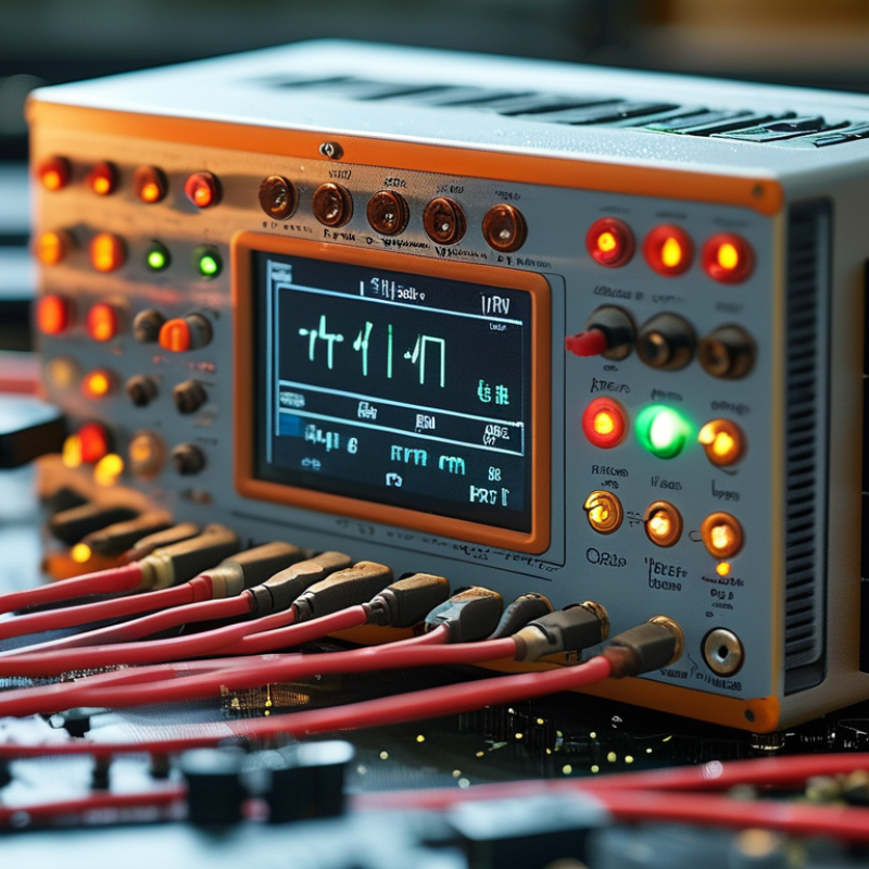
Define the System’s Power Requirements and Operating Conditions
Choosing the right power management PMIC starts with the system, not the component catalog. Define every power rail, input range, load profile, startup sequence, and shutdown condition. Include battery aging, cable loss, and worst-case ambient temperature. A 5 V rail drawing 2 A continuously may still demand sharp transient current during processor wake-up. Measure it.
Energy demand is becoming less forgiving. The International Energy Agency’s Energy and AI report estimates that data centers consumed about 415 TWh of electricity in 2024. It projects consumption may exceed 945 TWh by 2030. The Lawrence Berkeley National Laboratory’s 2024 United States Data Center Energy Usage Report also projects data centers could use 6.7% to 12% of U.S. electricity by 2028. These figures reinforce one point: efficiency must be evaluated across real operating conditions, not only at the nominal load.
Check conversion efficiency at light, typical, and peak loads. Review thermal rise inside the actual enclosure. Confirm current limits, ripple, sequencing, power-good timing, and fault recovery. Shorter is better. Sometimes.
A common engineering mistake is selecting a PMIC from the maximum current rating alone. That number can hide poor light-load efficiency or unstable behavior during rapid load changes. Laboratory tests should include cold starts, repeated sleep cycles, brownouts, and aged batteries. A spreadsheet helps, but it cannot replace measurements. Some assumptions will be wrong. Find them early.
How to Choose the Right Power Management PMIC? - Define the System’s Power Requirements and Operating Conditions
System power requirement definition matrix for comparing PMIC functions, electrical limits, thermal conditions, and operating modes before component selection.
| Power Domain | Required Voltage | Typical Load | Peak Load | Operating Condition | PMIC Selection Consideration |
|---|---|---|---|---|---|
| System Input | 5.0 V nominal 4.5–5.5 V operating range | System-dependent | Defined by the upstream adapter or battery source | Continuous operation with input transients during cable connection | Confirm input-voltage tolerance, undervoltage lockout, overvoltage protection, and input surge handling. |
| Digital Logic | 1.0–1.2 V | 0.35 A | 0.80 A during processor activity | Fast load changes between sleep and active states | Check peak current capability, transient response, output-voltage accuracy, and remote-sense support. |
| Memory Supply | 1.8 V | 0.20 A | 0.40 A during read/write bursts | Voltage must remain within the memory device’s specified tolerance | Prioritize low output ripple, stable regulation, power-good monitoring, and controlled startup. |
| I/O and Peripherals | 3.3 V | 0.55 A | 1.20 A when interfaces and sensors operate simultaneously | Intermittent loads from communication interfaces, storage, and sensors | Allow sufficient current margin and evaluate load-transient performance under worst-case peripheral activity. |
| Analog Circuitry | 3.3 V or 5.0 V | 0.08 A | 0.12 A | Noise-sensitive measurement and signal-conditioning circuits | Consider low-noise regulators, high power-supply rejection, low ripple, and physical separation from switching nodes. |
| Power-On Sequence | Multiple rails | Not applicable | Not applicable | Core rail enabled before I/O rail; reset released only after rails are stable | Select a PMIC with programmable sequencing, adjustable delays, enable inputs, and power-good outputs. |
| Standby Mode | Always-on rails: 1.8–3.3 V | 2–10 mA total | 25 mA during wake-up preparation | Long-duration low-power operation | Compare quiescent current, shutdown current, retention-rail behavior, and wake-up response time. |
| Efficiency Target | Application-dependent | 85–95% for switching rails | Maintain regulation at maximum rated load | Efficiency must be evaluated across light, typical, and full-load conditions | Review switching frequency, inductor requirements, light-load mode, thermal losses, and efficiency curves. |
| Output Ripple | Dependent on load sensitivity | Typically below 20–50 mV peak-to-peak for digital rails | May increase during fast load transients | Measured with the recommended layout, capacitors, and test bandwidth | Verify the PMIC’s output-capacitor requirements and assess ripple at the point of load, not only at the regulator pins. |
| Ambient Temperature | −20 °C to +70 °C | Normal operating range | Full rated load at the maximum ambient temperature | Enclosed equipment with limited airflow | Calculate junction temperature using power dissipation, thermal resistance, PCB copper area, and enclosure conditions. |
| Protection Requirements | All regulated outputs | Normal operation | Short circuit, overload, and input fault events | System must recover safely without permanent damage | Check current limiting, thermal shutdown, short-circuit recovery, overvoltage protection, and fault reporting. |
| Layout Constraints | PCB area limited | Compact placement preferred | Thermal and electromagnetic performance must remain acceptable | Multi-layer PCB with short switching-current loops | Confirm package size, external component count, inductor clearance, grounding strategy, and recommended PCB layout. |

We have over 30 years of experience in designing complete hydraulic systems, repairs and distribution of fluid power equipment and parts.
FOLLOW US ON :
Contact Details
Address:
4020 SE 45th CT.
Ocala, FL 34480
Phone No:
Email:
sales@cunninghamfluidpower.com