

What Is an Electro Hydraulic Valve and How Does It Work?
An Electro-Hydraulic Valve connects electronic control with hydraulic force. It receives an electrical signal, then directs pressurized fluid toward a cylinder or motor. A small coil may shift a spool, open a pilot stage, or regulate pressure. The result is controlled movement, braking, clamping, or lifting.
“Fluid power is the technology that uses pressurized fluids to transmit and control power.” — Anthony Esposito, author of Fluid Power with Applications. His definition provides a useful starting point, but an Electro-Hydraulic Valve involves more than pressure alone. Engineers must consider flow rate, response time, contamination, temperature, and actuator load. A valve that performs well on a test bench may react differently beside a hot pump or a vibrating machine.
The operating process becomes clearer through a simple example. A controller sends current to the solenoid. The magnetic force moves the valve spool. Fluid then travels through selected passages, creating pressure across the actuator. When the signal changes, the spool returns, often through a spring or proportional command. Small details matter. A clogged filter can slow movement. Low voltage can weaken the response. Excessive leakage can reduce holding force.
This explanation is not perfect. Real systems include delays, heat, friction, and pressure spikes. Those imperfections deserve attention. Understanding them helps technicians diagnose faults safely and helps designers select the correct valve architecture. This guide explains the main types, internal components, working sequence, practical applications, and maintenance factors behind an Electro-Hydraulic Valve.
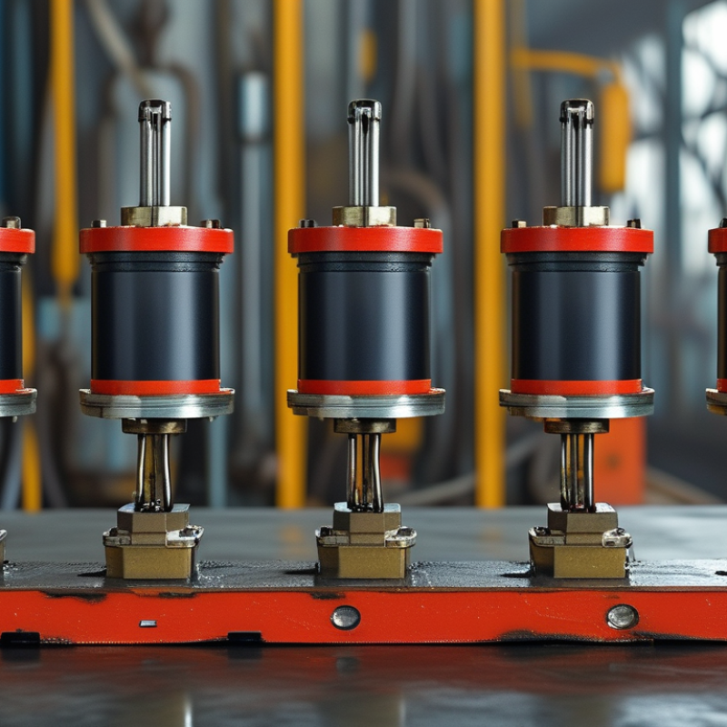
Electro-Hydraulic Valves: Definition and Basic Function
What Is an Electro Hydraulic Valve and How Does It Work?
An electro-hydraulic valve combines electrical control with pressurized fluid power. Its electrical section receives a signal from a controller. That signal moves a solenoid, motor, or proportional actuator. The actuator changes a spool or poppet position inside the valve body. Fluid then travels through selected passages.
In basic operation, an input signal represents a requested flow rate, pressure, or direction. The valve converts that request into mechanical movement. A spool may open gradually, allowing measured fluid flow to a cylinder or hydraulic motor. A directional version switches paths, while a pressure-control version limits or regulates force. This interaction gives machines smoother motion than a purely manual valve. Small errors matter. Contamination, wiring resistance, and coil heat can change the response.
From field inspections, technicians often verify supply voltage, connector condition, and fluid cleanliness before adjusting settings. They also compare commanded movement with actual pressure and travel. A slow response may indicate a clogged filter, worn internal surfaces, or an incorrect signal. Not every delay indicates valve failure. Temperature and load can mislead diagnosis. Reliable installation requires correct sizing, suitable seals, clean connections, and testing under realistic operating conditions. The details matter. A neat electrical signal does not guarantee perfect hydraulic movement.
| Data Dimension | Typical Information | Definition and Basic Function |
|---|---|---|
| Definition | Electrically controlled hydraulic valve | An electro-hydraulic valve uses an electrical input signal to control the direction, pressure, or flow of hydraulic fluid in a pressurized circuit. |
| Energy Conversion | Electrical signal to hydraulic action | An electronic command energizes a solenoid or drives an electro-mechanical actuator, which changes the position of a hydraulic control element. |
| Main Control Variables | Direction, pressure, and flow | Directional valves control actuator movement, pressure valves regulate system force, and flow-control valves adjust actuator speed. |
| Primary Components | Valve body, spool or poppet, actuator, spring, seals, and ports | The valve body guides hydraulic fluid, while the spool or poppet opens, closes, or restricts flow paths. Springs commonly return the valve to a defined position when the signal is removed. |
| Electrical Actuation | Solenoid, proportional actuator, or servo actuator | On/off solenoids provide discrete positions. Proportional and servo actuators allow more precise control of spool position, flow, or pressure. |
| Hydraulic Ports | Pressure, tank, and working ports | A typical directional circuit includes a pressure port connected to the pump, a tank or return port connected to the reservoir, and one or more working ports connected to an actuator. |
| Operating Sequence | Command, actuation, flow change, and response | The controller sends a signal, the actuator shifts the internal control element, hydraulic flow is redirected or metered, and the connected cylinder or motor responds. |
| Control Signal Types | Digital or analog | Digital signals generally produce an on/off response. Analog signals, such as voltage or current commands, can produce variable valve opening and smoother motion. |
| Common Valve Functions | Directional, pressure, and flow control | Directional valves determine movement direction; pressure valves limit or regulate pressure; flow valves control the rate of hydraulic fluid movement. |
| Typical Hydraulic Medium | Mineral-based or synthetic hydraulic fluid | The fluid transfers power, lubricates internal parts, and helps remove heat. The selected fluid must be compatible with the valve seals and operating conditions. |
| Response Behavior | Fast response with possible switching transients | Electro-hydraulic valves can react quickly, but response is affected by electrical delay, spool movement, fluid compressibility, pressure changes, and load characteristics. |
| Pressure Rating | Application-specific; commonly specified in bar or MPa | The allowable pressure depends on the valve design and must not be exceeded. The system rating is determined by the lowest-rated connected component. |
| Flow Rating | Application-specific; commonly specified in L/min | Flow capacity indicates how much hydraulic fluid can pass through the valve under defined pressure-drop conditions. Excessive flow can increase heat and reduce control accuracy. |
| Neutral or De-Energized Position | Normally closed, normally open, or defined center condition | When the actuator is not energized, the valve may block flow, connect ports, or unload the pump depending on its internal configuration and spring arrangement. |
| Feedback Options | None, position feedback, pressure feedback, or external sensor feedback | Feedback enables a controller to compare the desired and actual condition, improving accuracy in position, pressure, speed, or force control. |
| Advantages | Remote control, automation, precision, and high power density | Electrical control allows integration with sensors, programmable controllers, and safety systems while hydraulic power provides high force and compact actuator size. |
| Limitations | Fluid cleanliness, heat generation, leakage, and tuning requirements | Contamination can damage precision parts, throttling can generate heat, seals may wear, and proportional or servo systems may require careful adjustment. |
| Common Applications | Mobile machinery, industrial automation, presses, lifting systems, and material handling | Electro-hydraulic valves are used where electronic control and hydraulic power must work together to manage motion, force, speed, or load holding. |
| Maintenance Priorities | Filtration, fluid condition, electrical connections, seals, and leakage inspection | Regular maintenance helps preserve response quality and service life. Hydraulic cleanliness and correct fluid level are especially important for reliable operation. |
| Basic Safety Principle | Relieve stored hydraulic and electrical energy before servicing | Hydraulic systems can retain dangerous pressure after shutdown. Lockout procedures, pressure release, suitable protective equipment, and manufacturer-approved methods are essential. |

We have over 30 years of experience in designing complete hydraulic systems, repairs and distribution of fluid power equipment and parts.
FOLLOW US ON :
Contact Details
Address:
4020 SE 45th CT.
Ocala, FL 34480
Phone No:
Email:
sales@cunninghamfluidpower.com