How to Perform a Meter Test?
A Meter Test can help you check voltage, resistance, or continuity with a digital multimeter. The right test depends on what you are measuring and whether the circuit is energized. A wall outlet, a loose battery, and a disconnected wire require different settings and precautions. Guessing can damage the meter or produce a misleading reading.
Start by inspecting the meter, leads, and probe tips for cracks or exposed wire. Confirm the leads are in the correct sockets, then select the function and range specified by the meter’s manual. For resistance and continuity checks, disconnect power and discharge stored energy before touching the probes to a component. For voltage measurements, use a meter rated for the expected range, keep fingers behind the probe guards, and avoid touching bare metal. If you are unsure, stop. A reading is not worth a shock.
This guide explains how to choose a setting, make steady probe contact, and interpret common displays such as zero, OL, or a changing value. It also covers checking the meter against a known source before and after a voltage test, where appropriate and safe. Readings can vary with the device and conditions, so compare them with reliable product documentation rather than relying on one number alone. Small details matter. Even experienced users can overlook a damaged lead or an incorrect range; pause and check again.
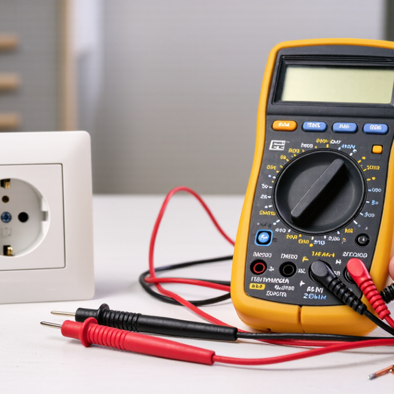
Identify the Meter Type and Define the Test Objective
Before testing, identify what the meter measures and how it reports results. A household electricity meter may be an older electromechanical unit or an electronic meter with interval readings. Check its nameplate, displayed units, pulse indicator, and any multiplier shown on the installation records. For water or gas meters, confirm the flow units and register type instead. Small details matter. The U.S. Energy Information Administration’s 2022 Electric Power Annual reported about 119 million advanced electricity meters, serving roughly 72% of U.S. customers. That variety makes a one-size-fits-all test plan unreliable.
Define the test objective before connecting equipment. Are you checking displayed energy, measurement accuracy, a suspected high bill, or communication between the meter and its system? Each goal calls for different evidence. An accuracy check needs a suitable reference source and documented test conditions; a communications check needs verified readings and timestamps. Record the meter’s starting display, load conditions, and instrument settings. Follow applicable procedures, and do not open sealed utility equipment. It is easy to over-test. A tidy checklist can still miss an unexpected multiplier, so pause when readings do not match the meter’s configuration.
Inspect the Meter, Leads, and Test Area for Safety
How to Perform a Meter Test?
Inspect the Meter, Leads, and Test Area for Safety
Before testing, look closely at the meter case, display, selector, and input sockets. A cracked housing, loose socket, or unreadable setting can turn a routine check into a hazard. Inspect each lead from probe tip to plug. Do not use leads with split insulation, bent tips, exposed metal, or damaged finger guards. Confirm the meter and leads are rated for the expected voltage and measurement category. Check that the leads are plugged into the correct sockets for the intended measurement. Small details matter.
Prepare the test area, too. Keep hands and the floor dry, clear away loose metal, and make sure you can stand steadily without reaching across energized equipment. Remove conductive jewelry. If the circuit’s rating or condition is unclear, stop and ask a qualified person. The U.S. Bureau of Labor Statistics reported 5,486 fatal work injuries in 2022; its data cover all work-related hazards, not meter testing alone. The same year, its workplace injury survey recorded about 2.8 million nonfatal cases in private industry. Those figures are broad context, not a measure of meter-related risk. A careful pre-use inspection can feel slow. It is still easy to miss a frayed lead when you are in a hurry, so pause and check again.
Select the Correct Settings and Connect the Test Leads
Choose the measurement before connecting the probes. Set the dial to voltage for a powered circuit, and match AC or DC to the source. For resistance or continuity, switch off power and discharge stored energy as the equipment instructions require. A quick pause helps. Check the meter’s category and voltage ratings against the circuit, and inspect the leads for cracked insulation or bent probe tips.
Insert the black lead into COM and the red lead into the socket marked for the measurement. Voltage usually uses the V socket; current may require a separate socket and a series connection. Never measure voltage with the red lead in a current socket. Select a range above the expected value if the meter is not autoranging. Touch the probes to the intended points without letting their metal tips bridge nearby terminals. Keep fingers behind the probe guards. Verify the meter on a suitable known reference before and after testing, when safe to do so. It is easy to rush this check, and that is exactly when a wrong setting can produce a misleading reading or damage the meter.
How to Perform a Meter Test? - Select the Correct Settings and Connect the Test Leads
| Test purpose | Meter setting | Lead connections | How to connect and read | Important check |
| Check a battery or DC supply | DC voltage (V⎓); choose a range above the expected voltage if the meter is not auto-ranging. | Black lead: COM. Red lead: V/Ω input. | Place the probes across the supply: red on positive and black on negative. Read the displayed voltage; a minus sign indicates reversed probe polarity. | Confirm the meter’s voltage rating is suitable for the circuit. |
| Check an AC outlet or AC circuit | AC voltage (V~); select a range above the expected voltage if needed. | Black lead: COM. Red lead: V/Ω input. | Measure between the appropriate conductors using insulated probes and a safe method suitable for the installation. | Use a meter and probes rated for the circuit’s voltage and measurement category. Do not touch exposed metal probe tips. |
| Check continuity of a wire or fuse | Continuity (sound-wave or buzzer symbol). | Black lead: COM. Red lead: V/Ω input. | With the circuit de-energized, touch one probe to each end of the conductor or fuse. A beep or low resistance usually indicates a continuous path. | Verify power is off and discharge capacitors as appropriate before testing. |
| Measure resistance | Resistance (Ω); choose a suitable range if the meter is not auto-ranging. | Black lead: COM. Red lead: V/Ω input. | Place one probe at each end of the component or across its terminals. Read the resistance shown on the display. | Turn off power first. In-circuit components can affect the reading; isolate a component when necessary. |
| Test a diode | Diode test (diode symbol). | Black lead: COM. Red lead: V/Ω input. | With power off, connect red to the anode and black to the cathode. Reverse the probes to compare the readings; a forward-voltage reading in one direction and an open indication in the other is typical for a working diode. | Readings vary by diode type and circuit conditions. Isolate the diode if other components affect the result. |
| Measure current | AC current (A~) or DC current (A⎓); begin on the highest suitable range when the current is unknown. | Black lead: COM. Red lead: the correctly rated mA/μA or A input. | Open the circuit and connect the meter in series so current flows through it. For DC, observe the expected polarity; move the red lead to the V/Ω input after the test. | Never connect a meter in current mode directly across a voltage source. Check the input fuse and current limit before testing. |
Safety reminder: Inspect the meter and leads for damage, use equipment with ratings appropriate to the circuit, and follow the meter’s instructions. If you are unsure how to test an energized circuit safely, ask a qualified electrician.
Take the Measurement and Record the Readings
Before taking a reading, identify what you are measuring: voltage, resistance, or current. Select the matching meter function and a suitable range, if the meter is not automatic. Check that the leads are intact and seated in the correct sockets. Small details matter. For electrical measurements, follow the meter’s instructions and safety ratings; do not touch exposed metal or test a circuit beyond your training.
Place the probes at the intended measurement points and keep your hands steady. For voltage, connect across the two points; for resistance, make sure the circuit is de-energized first. Wait for the display to settle, then record the value, unit, range, and test location. Include the date and relevant conditions, such as whether a device was running. A reading without context can be hard to interpret later.
If the display fluctuates, note the range you observed rather than choosing the number that looks best. Repeat the measurement once, using the same points and setup, and record both results if they differ. I would also note anything unusual, like a loose connection or a warm component; it is easy to overlook these details while concentrating on the display. Don’t erase an unexpected result. Verify the setup and investigate safely before relying on it.
Compare Results with Specifications and Restore the Setup
Compare each reading with the meter’s published accuracy specification for the selected range, not just the displayed value. Check the test conditions, including temperature, input signal, and lead placement. A reading can look convincing while a loose probe quietly changes it. Small details matter. Record the measured value, range, reference instrument, and any uncertainty so another technician can follow the comparison.
Treat uncertainty as part of the decision. NIST Technical Note 1297 explains that an expanded uncertainty using a coverage factor of 2 corresponds to roughly 95% coverage when its assumptions are met. EURAMET’s calibration guidance for digital multimeters likewise emphasizes documenting measurement uncertainty and test conditions. If the result and its uncertainty approach or exceed the meter’s tolerance limit, do not call it a pass by rounding. Repeat the measurement, inspect the connections, and escalate any unresolved discrepancy.
After testing, remove the probes from the circuit before changing connections or restoring equipment. Return the leads to their proper sockets, clear temporary test links, and reset the meter to a safe, known state. Then restore covers and wiring, and verify the equipment operates normally. It is easy to miss one lead. I still check the setup against my notes, even when the test seemed routine. Keep the results with the meter’s service record, including any adjustment or follow-up needed.
Meter Test: Compare Results with Specifications
Result: Pass. The meter’s errors at 1 V, 5 V, and 10 V are within the illustrative ±0.5% limits. After recording the readings, disconnect the test source and restore the meter and test setup to their normal configuration.