

What Are the Top Permanent Formwork Magnet Types?
Permanent Formwork Magnets hold steel forms and embedded components in position without relying on drilled fixings. Yet the term covers several designs, not one universal tool. Understanding the main Permanent Formwork Magnet types helps project teams match a magnet to the form profile, concrete load, and working conditions.
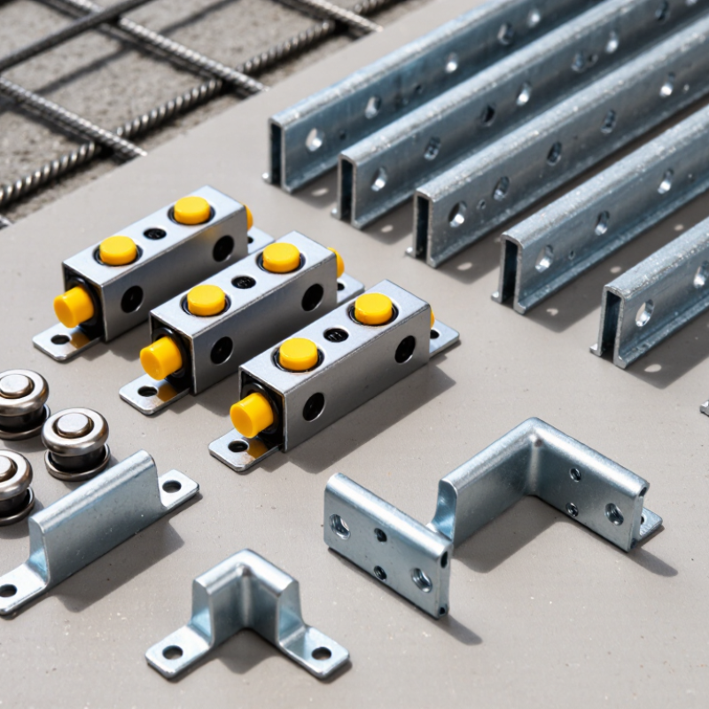
Common options include compact button magnets, push-button assemblies, magnetic side-rail systems, and corner or edge magnets. Button magnets suit many standard form setups, while push-button designs can make release easier for crews wearing gloves. Side-rail magnets provide a longer contact area for compatible rails. Corner magnets help secure form edges where alignment is particularly important. Small differences matter. A magnet’s holding force depends on more than its advertised rating. Steel thickness, contact quality, surface contamination, vibration, and installation position can all affect performance.
This guide compares these types by design, typical use, handling, and practical limitations. It also considers details that are easy to overlook, such as access for removal and compatibility with the formwork system. A clean catalog comparison may not reflect a crowded site or a slightly uneven steel surface. That is worth remembering. No type is automatically best for every project. Selection should follow manufacturer guidance and the actual setup, with trial fitting where conditions are uncertain.
Define Permanent Formwork Magnets by Design, Mounting Method, and Holding Force
Permanent formwork magnets are commonly grouped by their construction. Box-style units place permanent magnets inside a steel housing, often with a switch or release mechanism for positioning and removal. Compact button magnets suit smaller contact areas, while integrated designs combine magnets with a rail or adapter that supports a particular formwork profile. The housing matters: it protects the magnetic assembly and provides a practical surface for handling. Small detail, big effect.
Mounting method changes how a magnet fits the job. Some units sit directly on a steel formwork table; others use bolts, clamps, or profile-specific adapters to hold panels in place. On site, check that the contact surface is flat and free of concrete residue. A thin gap or uneven plate can reduce grip. It is easy to overlook this during a quick setup.
Holding force is usually stated as a rated pull force under controlled conditions, not a guarantee of performance in every installation. Actual grip depends on steel thickness, surface condition, load direction, and vibration during concrete placement. A vertical pull test does not fully describe resistance to sideways movement. Compare ratings using the same test basis, then verify the setup with the formwork supplier’s guidance. I would not choose by the largest number alone.
| Magnet Type | Design and Activation | Typical Mounting Method | Indicative Nominal Holding Force | Common Applications |
|---|---|---|---|---|
| Push-button magnetic box | A compact permanent-magnet unit with a top button or plunger that switches the magnetic circuit between holding and release positions. | Placed on a clean steel casting bed; a compatible adapter, bolt, or clamp connects the box to the formwork. | About 10–30 kN per unit for many standard sizes; capacity varies by model and contact conditions. | Reusable side forms, stop-ends, and modular formwork on steel precast beds. |
| Lever-operated magnetic box | A permanent-magnet assembly switched on or released by a manual lever, often providing mechanical leverage for operation. | Set onto the steel bed and connected to the formwork through an adapter plate or fastening interface. | About 10–30 kN per unit for common units; larger designs may be rated higher. | Applications where operators prefer a lever action or need a practical release mechanism for repeated setup changes. |
| Heavy-duty magnetic box | A larger or multi-magnet permanent assembly designed for higher clamping capacity and demanding formwork loads. | Positioned directly on the steel bed and attached to the formwork with a suitably rated adapter or mechanical connection. | Often about 30–50 kN or more per unit, depending on the design and test conditions. | Longer, taller, or more heavily loaded forms and precast setups that require greater clamping capacity. |
| Magnetic side-form or edge clamp | A low-profile permanent-magnet unit shaped to secure side forms or edge profiles close to the casting surface. | Placed against the steel bed; the side form is retained by an integrated clamp, adapter, or bolted connection. | Typically about 5–20 kN per unit; the required number and spacing depend on form height and concrete pressure. | Thin or low-profile side forms, edge profiles, and configurations with limited clearance. |
| Magnetic rail or strip system | A continuous or modular formwork element incorporating multiple permanent-magnet units or magnetic contact zones. | Laid along the steel bed and aligned with the formwork; individual magnetic sections hold the rail or attached profile in place. | Rated by unit, module, or length rather than by one universal figure; capacity depends on magnet spacing and system design. | Repeated production layouts, long straight forms, and setups where faster alignment along a bed is useful. |
| Selection note: Holding-force figures are indicative, not directly interchangeable between products. Actual performance depends on the magnet’s rated test method, steel-bed thickness and flatness, surface cleanliness, contact area, load direction, form geometry, and the number and spacing of magnets. Check the manufacturer’s technical rating and the formwork load calculation for the specific application. | ||||
FAQS
They suit long, straight panel edges. Continuous support can help limit movement during concrete placement. Check alignment where panels meet.
Gaps, dirt, paint buildup, or welds can reduce effective contact. Even a small gap matters. Clean the steel first.
Magnet boxes provide concentrated holding force at table or frame contact points. They are useful for removable, localized fixing. Uneven surfaces may make them rock.
They connect magnets to different formwork profiles. This adds flexibility, but creates another alignment point to inspect.
Match its shape to the formwork profile. Button magnets suit compact, flat steel surfaces; rails support long edges. Box-style systems can suit adjustable or unusual profiles.
No. Consider contact area, sliding resistance, release access, and panel geometry. Test the full assembly on the actual formwork.
Pour height, placement rate, concrete temperature, and concrete weight all matter. A fast, tall pour can create different pressure from a shallow placement.
Look for rocking, gaps, and movement under load. Check the real surface, not just a clean sample. People still skip this sometimes; it deserves a second look.

We have over 30 years of experience in designing complete hydraulic systems, repairs and distribution of fluid power equipment and parts.
FOLLOW US ON :
Contact Details
Address:
4020 SE 45th CT.
Ocala, FL 34480
Phone No:
Email:
sales@cunninghamfluidpower.com