

Why Choose an Optical Attenuator for Fiber Networks?
Why Choose an Optical Attenuator for Fiber Networks?
Fiber networks are designed to carry light efficiently across long distances. However, excessive optical power can damage receivers, create measurement errors, and reduce link stability. An Optical Attenuator controls that power without interrupting the signal path. It acts like a carefully adjusted dimmer for light traveling through glass.
Professor Govind P. Agrawal, a respected fiber-optics researcher and author, describes the principle clearly: “An optical attenuator is used to reduce the optical power of an optical signal.” That simple function has practical importance. During installation, technicians may connect a 10 dB attenuator before a sensitive receiver. They then check the signal with a calibrated optical power meter. The result is safer equipment and more predictable performance.
The choice is not automatic.
Fixed attenuators suit stable links. Variable attenuators help during testing, commissioning, and changing network conditions. Engineers must also check connector type, wavelength range, return loss, insertion loss, and maximum power ratings. A poorly matched device may introduce reflection or unnecessary signal loss. In real cabinets, even dust on a connector can distort measurements.
Experience teaches an uncomfortable lesson: stronger light is not always better. Network designers sometimes focus on transmitter power and overlook receiver limits. That oversight can become expensive. An Optical Attenuator offers a controlled correction, but it cannot repair a damaged connector or poor fiber splice. Careful inspection still matters.
This article explores how Optical Attenuators support reliable fiber networks, accurate testing, and long-term equipment protection. Their value becomes clearest when power levels, network distances, and receiver tolerances are considered together.
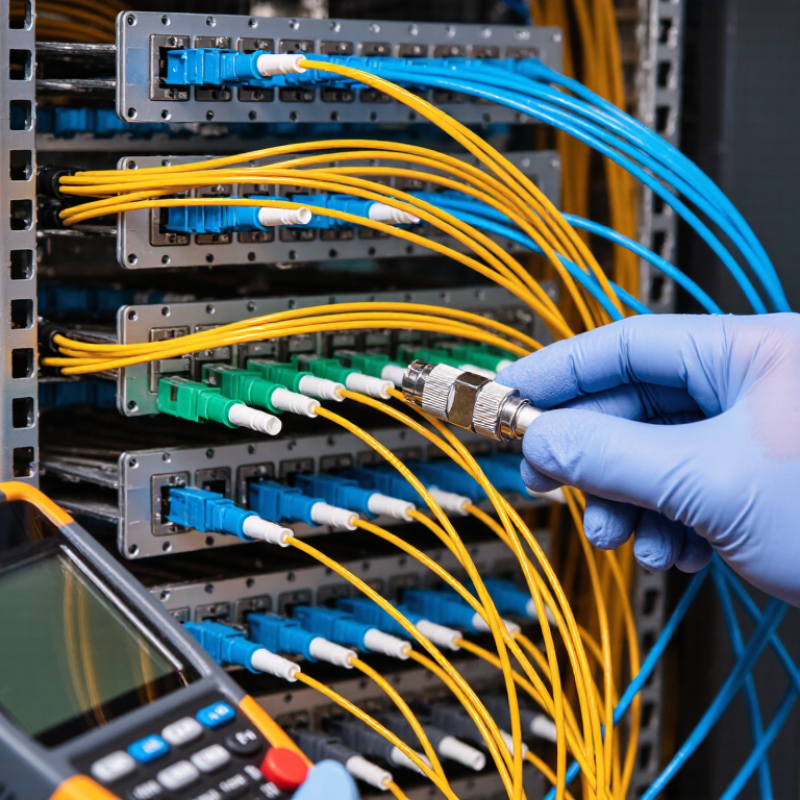
What Is an Optical Attenuator in Fiber Networks?
An optical attenuator is a passive device that reduces optical power in a fiber network. It prevents a receiver from becoming overloaded when the incoming signal is too strong. The device adds controlled loss, measured in decibels (dB), while allowing data to continue through the fiber.
Attenuators may be fixed or adjustable. A fixed attenuator provides one defined loss, such as 3 dB or 10 dB. An adjustable model allows technicians to tune power during commissioning. Some designs connect inline with patch cords, while others use connector-mounted formats. In practice, I check the optical power meter before choosing the attenuation value. The target should remain within the receiver’s operating range, not simply become “as low as possible.”
That distinction matters.
A common field mistake is adding attenuation without checking the complete link budget. Fiber length, splices, connectors, and splitters already create loss. Too much extra loss can reduce the safety margin and cause unstable service. I have also seen dust on connector end faces mistaken for an attenuator problem. Cleaning, inspection, and repeat measurements should come before replacement. Adjustable attenuators are useful during testing, but they can introduce uncertainty if settings are changed carelessly. Record the measured power, wavelength, and attenuation value at both ends. Small oversights remain possible, especially when technicians rely on labels instead of actual measurements.
Why Choose an Optical Attenuator for Fiber Networks? - What Is an Optical Attenuator in Fiber Networks?
| Data Dimension | Optical Attenuator Information | Why It Matters in a Fiber Network |
|---|---|---|
| Basic Definition | A passive optical component that reduces optical power by a specified amount, measured in decibels (dB). | It helps prevent excessive optical power from reaching a receiver and keeps the link within its permitted operating range. |
| Primary Function | Introduces controlled insertion loss without requiring electrical power or network configuration. | It offers a simple way to balance optical levels during installation, testing, or network upgrades. |
| Typical Attenuation Values | Common fixed values include 1, 2, 3, 5, 10, 15, and 20 dB. Variable models can provide an adjustable attenuation range. | The correct value allows the received power to remain above receiver sensitivity while avoiding overload. |
| Common Wavelengths | Available for common single-mode operating windows such as 1310 nm, 1490 nm, 1550 nm, and 1577 nm; multimode versions commonly support 850 nm. | Wavelength compatibility is essential because attenuation may vary across the operating spectrum. |
| Fiber Type | Designed for either single-mode fiber, multimode fiber, or a specified fiber category. | Using the appropriate fiber type helps maintain coupling efficiency and predictable optical performance. |
| Attenuator Type | Fixed attenuators provide a preset loss; variable attenuators allow adjustment; inline attenuators are installed directly in the fiber path; connector-style attenuators attach to a port. | The form factor can be selected according to installation space, adjustment requirements, and maintenance needs. |
| Insertion Loss | The specified attenuation is the intentional loss; total link loss also includes connector, splice, and fiber losses. | Link-budget calculations must include every loss component rather than considering the attenuator alone. |
| Return Loss | Quality passive attenuators are specified with a return-loss value, often dependent on connector polish and construction. | Higher return loss generally means less reflected power, which is important for sensitive transmitters and bidirectional systems. |
| Maximum Optical Power | The permissible input power depends on the attenuator design, wavelength, and operating environment; specifications must be checked before deployment. | Operating within the rated power prevents thermal damage and long-term performance degradation. |
| Connector Compatibility | Common connector interfaces include LC, SC, ST, and FC, with connector gender and polish options selected for the installation. | Correct connector matching reduces installation errors, unwanted reflections, and additional connection loss. |
| Network Applications | Used in fiber-to-the-home access links, data center interconnections, telecommunications transport links, laboratory testing, and optical monitoring. | It supports different link lengths and optical budgets without replacing the entire transmission system. |
| Main Advantage | Passive operation, compact size, simple installation, and predictable attenuation. | It provides a cost-effective method for correcting optical power levels with minimal maintenance. |
| Selection Principle | Choose the attenuation value, wavelength range, fiber type, connector, power rating, and environmental specification required by the link budget. | A properly selected attenuator improves receiver protection and network stability without creating excessive signal loss. |

We have over 30 years of experience in designing complete hydraulic systems, repairs and distribution of fluid power equipment and parts.
FOLLOW US ON :
Contact Details
Address:
4020 SE 45th CT.
Ocala, FL 34480
Phone No:
Email:
sales@cunninghamfluidpower.com